 English
 русский
News
Home / News / Industry News / CNC Part Drawing Guide: Everything to Include Before You Machine a Part

 English
 Search
Suzhou Heimat Precision Machinery Co., Ltd.
+86-18118122885
joy.qian@szhengmai.com
A CNC part drawing is the document that follows your part from the design desk to the machine bed. It tells the machinist what the finished piece must measure, how smooth each surface needs to be, and which features genuinely matter to how the part works. When it is clear, the first article comes off the machine ready for inspection. When it is vague, everyone spends the week trading emails about a chamfer.
We have machined custom parts from drawings for years at Suzhou Heimat Precision Machinery, and the pattern never changes: the quality of the drawing sets the ceiling on the quality of the conversation. This guide covers what a CNC part drawing should contain, how to put one together, and the mistakes that cause the most rework.
Most projects today begin as a 3D CAD model, and that model is very good at showing form and fit. It is a poor contract, though. A STEP file will not tell a machinist which face is the datum, whether a hole is a clearance hole or a press fit, or whether a small scratch on an unseen surface is acceptable.
A drawing does. It turns design intent into measurable requirements, and those requirements become the basis of inspection. If your supplier quotes from a solid model and then measures against a drawing, the drawing decides the argument about what was ordered. That is why we ask for one even when the model is clean and complete.
There is a practical gain, too. Clear dimensions speed up programming and setup planning, shorten first article inspection, and give both sides an objective reference when a measurement is questioned.
Drawings vary by industry and by shop, but the ones that work share the same anatomy.
Part name, part number, revision, material, scale, units, projection method, designer, date, and sheet number. Revision is the field people forget, and it is the one that turns a good part into scrap.
Orthographic views carry the geometry. An isometric view shows orientation at a glance. Section views expose internal features such as bores and pockets, and detail views enlarge small features so their dimensions can be read without straining.
Dimension the part the way it will be inspected. Choose datums that reflect how the part locates in its assembly, then dimension from those datums instead of chaining every dimension off one edge. Avoid duplicate or conflicting dimensions, because they force the machinist to guess which one you meant.
A general tolerance block covers the features that are not critical, and specific tolerances cover the ones that are. Geometric dimensioning and tolerancing adds flatness, perpendicularity, position, and runout where function depends on them. Tolerance what needs tolerancing and no more, since tightening everything raises cost without improving the part.
Name the material with its condition, for example 6061-T6 or 304 stainless. Add heat treatment, surface finish in Ra, plating or anodizing, deburring expectations, and any inspection or documentation requirement. Notes written inside the CAD model do not travel with a PDF, so anything essential belongs on the sheet.
| Drawing element | What it tells the machinist | Mistake that costs the most |
|---|---|---|
| Title block | Part identity, revision, material, units, and projection angle | Revision left unchanged after an update |
| Orthographic views | Overall geometry and how features relate to one another | A missing view that forces the machinist to guess depth |
| Section and detail views | Internal bores, pockets, and small features at a readable scale | Section omitted on a part with internal cavities |
| Dimensions and datums | Which measurements define the part and where they are taken from | Chained dimensions with no datum reference |
| Tolerance block and GD&T | How much variation is acceptable on each feature | Tolerancing every feature equally, which raises cost |
| Notes and finish callouts | Material condition, surface finish, deburring, and inspection | Requirements kept in the model instead of the sheet |
If you are starting from a blank sheet, this order keeps you out of trouble.
Some applications punish a loose drawing faster than others. Aerospace parts are a good example: a shaft diameter that drifts by a few microns can change how a bearing seats, and the fit is rarely adjustable later.
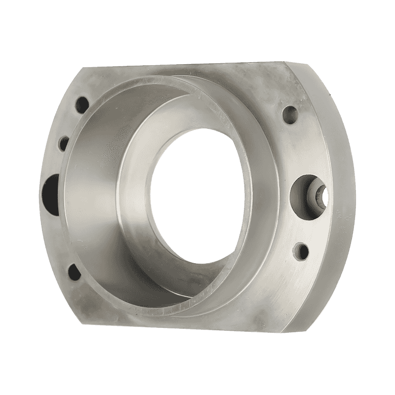 Customized High Precision Axis Parts for Aerospace EquipmentPrecision axis parts for aerospace equipment, where tight tolerances and strict quality control matter for reliable assembly.View Product →
Automation equipment behaves the same way. Robot arm brackets, mounting plates, and gripper components are usually assembled with parts from several suppliers, so position tolerances on hole patterns decide whether the machine goes together on the first attempt.
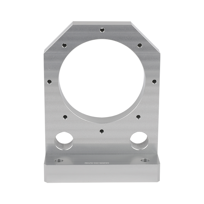 Automated Robotic Arm High-Precision CNC Machined PartsCNC-milled high-precision parts for automated robotic arms and production line equipment, where hole-pattern tolerances affect multi-supplier assembly.View Product →
Medical devices add a documentation layer on top of the same geometry problems. Material traceability, edge quality, and cleaning requirements all need to appear on the drawing rather than in a conversation.
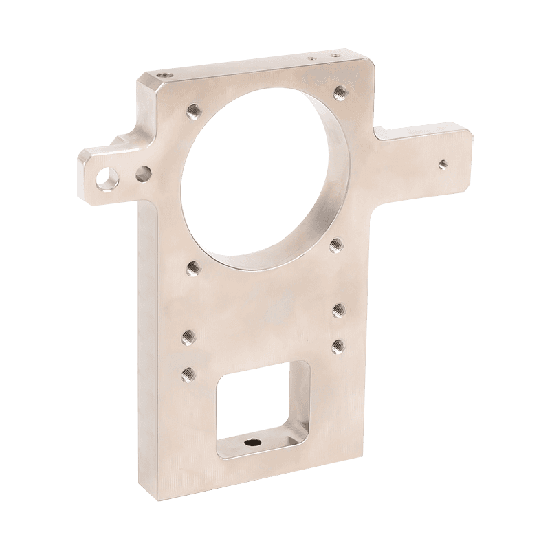 Customized Medical Equipment High-Precision Parts in 316LHigh-precision medical equipment components machined from 316L, for applications where traceability, edge quality, and cleaning documentation matter.View Product →
A drawing reaches our engineering team first. We look at the geometry, check whether the callouts match the equipment we have, and flag anything that will be difficult, expensive, or simply not achievable before we quote. Our machining centers, CNC lathes, wire cutting machines, and inspection equipment cover a wide range of part sizes, and we would rather raise a question at the quoting stage than surprise you during production.
From there the job goes to programming and setup, then to first article inspection. Holding dimensions across a full batch is a separate discipline with its own habits, which we discussed in our note on how dimensional accuracy is kept consistent during machining. Work is managed under ISO 9001 and ISO 14001 systems, and finished parts ship to customers in more than twenty countries.
None of this is complicated, and your drawing does not need to be perfect before you send it. If something is unclear, say so in a note and we will ask about it. A drawing that invites a question is far better than a drawing that hides one, because a question costs ten minutes and a scrapped batch costs a week.
Send over your drawing and model, and our engineers will review the callouts, confirm what our machines can hold, and come back with a quote. Get in touch whenever you are ready.
If you have any questions, please fill out the contact form at the bottom of the page and contact us.
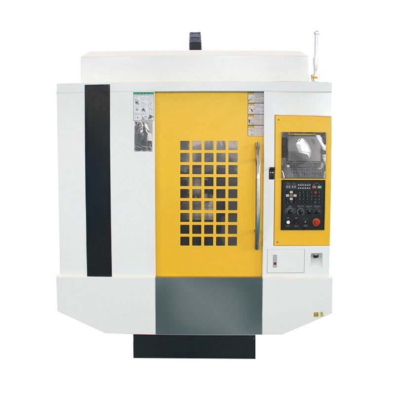 CNC Drilling and Tapping Machin
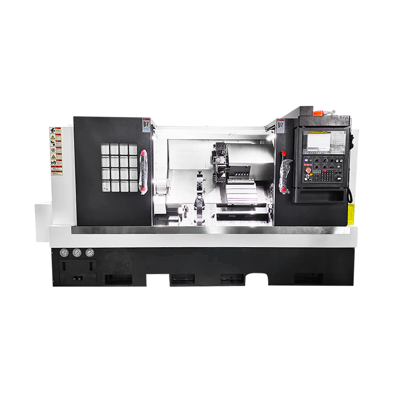 CNC Lathe Machine
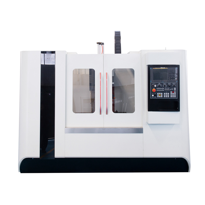 CNC Machine
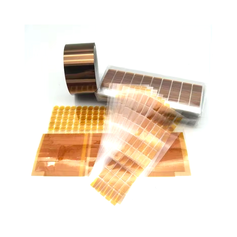 Cutomized Die-Cutting Products for Electronics Industry
 New Energy Automation Die Cutting Products
 Customeized Die-Cut Products in Package Industry
 Bespoke Touch Screen for Gaming and Entertainment Devices
 Custom Touch Screen in Smart Home Industry
 Customized Personalized Touch Panel Screen
 Design Manufacturing and Assembly of Special Customized Custom Electrical Cabinet
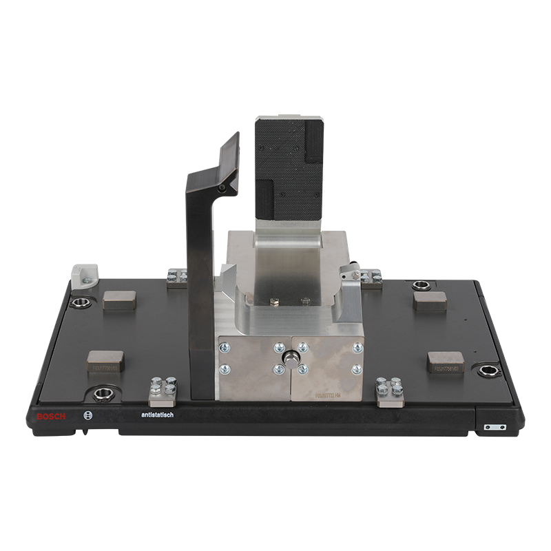 Industrial Robot Automatic Production Line Design Manufacture and Assembly
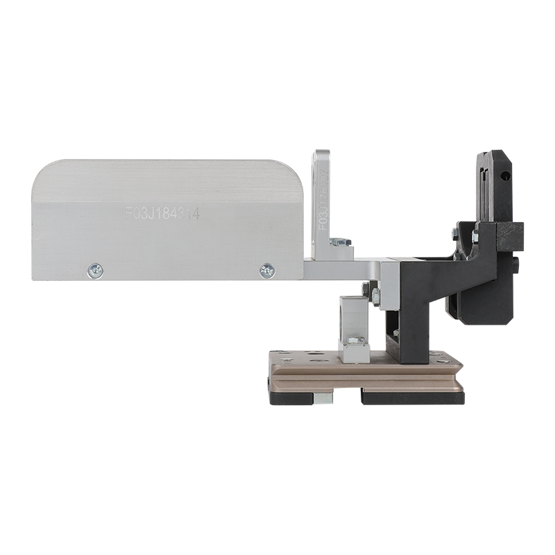 Customized Design Automation Equipment

+86-18118122885

+86-512-66233336

joy.qian@szhengmai.com

No. 8, Guangdian Road, Guangfu Town, Wuzhong District, Suzhou, Jiangsu, China.
Copyright © 2023 Suzhou Heimat Precision Machinery Co., Ltd. All Rights Reserved.Custom CNC Parts Processing Manufacturers

|
 Previous