 English
 русский
News
Home / News / Industry News / How to Prepare a CNC Turning Part Drawing That Machinists Can Machine Right

 English
 Search
Suzhou Heimat Precision Machinery Co., Ltd.
+86-18118122885
joy.qian@szhengmai.com
A CNC turning part drawing is the quiet agreement between the engineer who designed a component and the machinist who cuts it. On a lathe the workpiece spins and the tool travels, so every feature lives on or around an axis of rotation. When a drawing respects that geometry, programming is quick, the first article passes inspection, and nobody argues about which face was meant to be the datum. When it does not, even a well-run shop has to stop and ask.
We have reviewed a lot of turning drawings here at Suzhou Heimat, from single prototypes to repeating production parts for automation, energy and medical equipment. What follows is the practical version of what the shop floor has taught us: what belongs on the sheet, what the 3D model should carry, and which details quietly decide whether a drawing is easy to machine or expensive to interpret.
A milled part usually needs three orthographic views plus an isometric, because material comes off from many directions. A turned part is a solid of revolution. One well-chosen longitudinal view, with all diameters referenced to the centerline and all lengths referenced to a single face, often tells the whole story. Add an end view for cross-holes or flats and a section through an internal bore, and the geometry is fully defined.
That simplicity traps people who mostly design prismatic parts. Turning drawings rarely fail because a shape is missing. They fail because the dimensions are arranged the way a milling drawing would arrange them: measured between edges, chained from both ends, or written as radii where a diameter belongs.
Before we quote or program anything, we look for the same handful of blocks. A drawing missing one of them is still workable; a drawing missing four usually generates an email.
| Block | What it should contain |
|---|---|
| Title block | Part number, revision, material and condition, units, scale, general tolerance, designer and approver |
| Main longitudinal view | Full profile with diameters, lengths, chamfers, fillets, grooves and thread callouts |
| End or section views | Cross-holes, flats, keyways, internal bores, and anything unreadable from the side |
| Detail views | Zoomed callouts of small radii, relief grooves or seal seats |
| Datums | At least one axial datum face, with the centerline as the radial reference |
| Notes | Deburring, surface finish, heat treatment, marking and inspection expectations |
When a drawing is exported from a 3D model, the model and the sheet must agree. If they do not, we follow the drawing, because that is what the customer signs off — but we will always ask first.
Turning dimensions follow a few conventions that make an operator's life easier. None are exotic, yet all are frequently skipped.
Our turning cells are set up around exactly these conventions, which is part of the reason prototypes move quickly from drawing to first article.
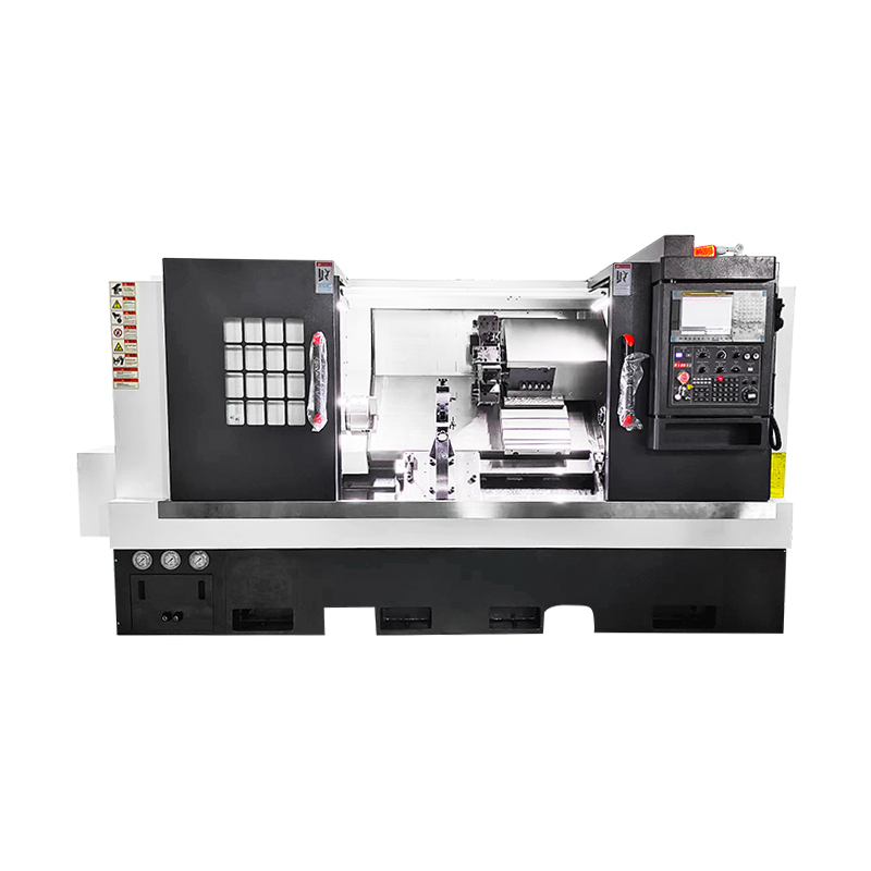 CNC Lathe Machine for Precision Turning WorkReview this CNC lathe for turning work where defined general tolerances help move prototypes from drawing to first article.View Product →
General tolerances do a lot of quiet work. A note such as ISO 2768-m means every untoleranced dimension has a defined limit, which removes dozens of potential questions. Features that genuinely matter then get their own callouts.
On turned parts the critical callouts are usually radial: cylindricity on a bearing seat, total runout between a shaft and a shoulder face, perpendicularity of a flange face to the axis, and position with a diametral zone between two bores. Surface roughness belongs next to the surface it applies to, expressed as an Ra value with a machining symbol rather than a note that says "smooth". Every tightened tolerance costs cycle time, tooling and inspection, so tighten only what the function needs.
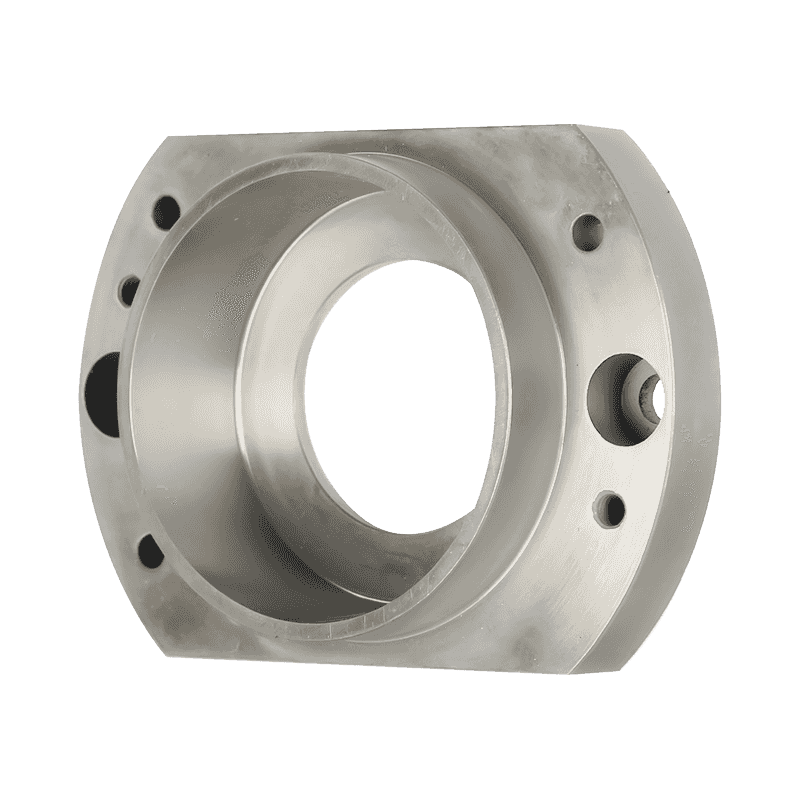 Customized High Precision Axis Parts for Aerospace EquipmentView customized axis parts for aerospace equipment where high precision and reliability matter, with critical radial callouts tightened only as function requires.View Product →
We wrote a longer explanation of what tolerances CNC machining can realistically hold if you want the numbers behind that trade-off.
Material and condition top the list. "304 stainless" is a start; "304 stainless, annealed, ASTM A276" is a specification. The same applies to aluminium alloys and engineering plastics, where two similar-sounding grades behave very differently once the tool touches them.
Then finish: anodising type and colour, passivation, plating thickness, powder coat reference, or simply "as machined, edges deburred". Add heat treatment and hardness where relevant, and state whether it happens before or after finish machining, because that changes the process routing.
Finally, the practical instructions. How should parts be marked? Does the customer want a first article inspection report or material certificates? A few lines here replace a long email thread.
Not every project starts with a finished drawing. Customers send hand sketches, photos of a worn part, or a rough model with a verbal description. That is a normal starting point for custom work, and turning it into something manufacturable is part of the service.
When we take on that step, we confirm the critical interfaces first — bore diameters, shaft fits, thread sizes, mounting hole patterns — then build the rest of the geometry around them. The result comes back for approval before any metal is cut, so nobody pays for our interpretation of an ambiguous feature.
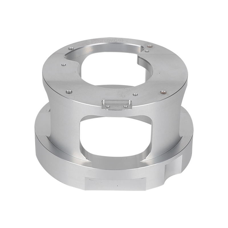 Customized CNC Parts for Automation EquipmentConsider these customized CNC parts for production line equipment and robotic arms, with critical interfaces confirmed before machining so ambiguous features are resolved early.View Product →
If a drawing is sitting on your desk and you are not sure it says enough, send it to us. We will tell you what we can machine as-is and what we would change, usually within a day and usually in fewer words than you expect.
If you have any questions, please fill out the contact form at the bottom of the page and contact us.
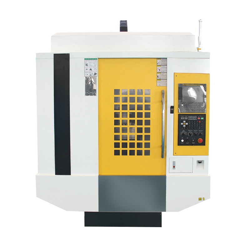 CNC Drilling and Tapping Machin
CNC Lathe Machine
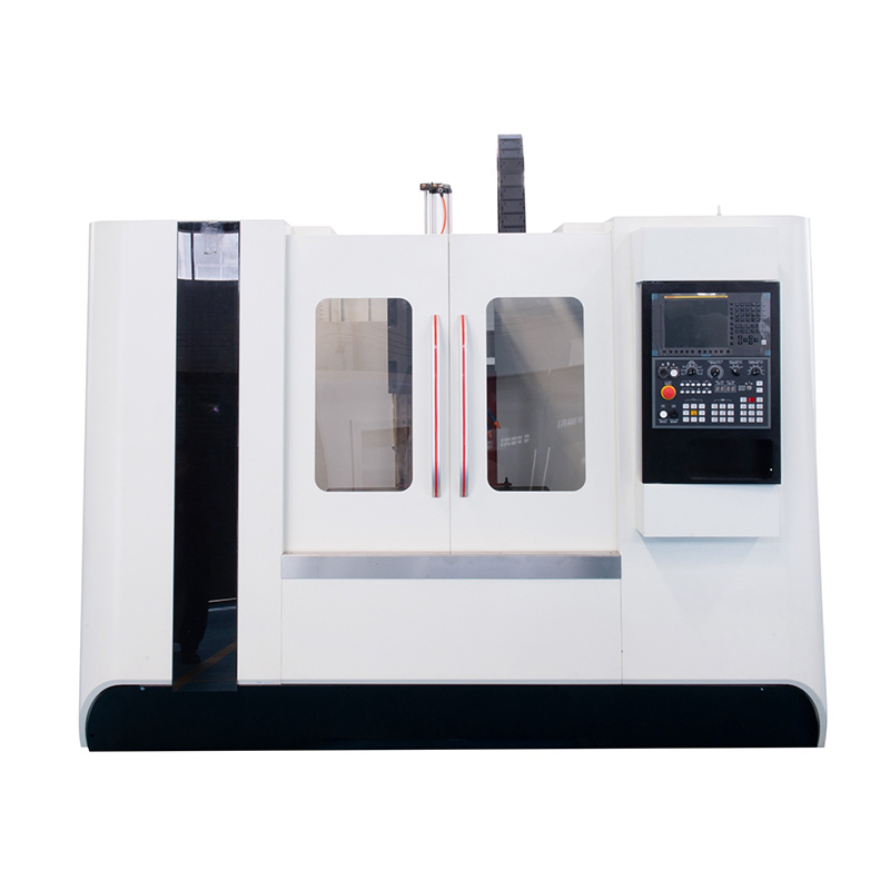 CNC Machine
 Cutomized Die-Cutting Products for Electronics Industry
 New Energy Automation Die Cutting Products
 Customeized Die-Cut Products in Package Industry
 Bespoke Touch Screen for Gaming and Entertainment Devices
 Custom Touch Screen in Smart Home Industry
 Customized Personalized Touch Panel Screen
 Design Manufacturing and Assembly of Special Customized Custom Electrical Cabinet
 Industrial Robot Automatic Production Line Design Manufacture and Assembly
 Customized Design Automation Equipment

+86-18118122885

+86-512-66233336

joy.qian@szhengmai.com

No. 8, Guangdian Road, Guangfu Town, Wuzhong District, Suzhou, Jiangsu, China.
Copyright © 2023 Suzhou Heimat Precision Machinery Co., Ltd. All Rights Reserved.Custom CNC Parts Processing Manufacturers

|
