 English
 русский
News
Home / News / Industry News / CNC Turning Machine Working: Process, Operations, and Practical Shop Tips

 English
 Search
Suzhou Heimat Precision Machinery Co., Ltd.
+86-18118122885
joy.qian@szhengmai.com
A lathe is one of the most honest machines on any shop floor. Clamp a blank, spin it, push a sharp tool into the surface, and material comes away as a ribbon or a spray of chips. Everything else — servo drives, encoders, a controller reading thousands of lines of code — exists to make that single idea repeatable. That is also the clearest way to understand CNC turning machine working: not as a checklist of features, but as a sequence of decisions about speed, force and geometry. What follows is the cycle as we see it every day at Suzhou Heimat Precision Machinery, from the first setup sheet to the last inspection report.
The workpiece turns; the tool does not. A blank is gripped in a chuck or collet and rotated at a set spindle speed, while a single-point tool travels along the X and Z axes and peels material from the outside diameter. This is the opposite of milling, where the cutter rotates and the part stays still. Because the rotating part is its own reference, turning suits anything round: shafts, bushings, flanges, fittings, valve bodies, connector housings and the long list of rotational components buried inside automation equipment.
A basic two-axis lathe handles external diameters, internal diameters and facing. Add a turret with live tooling and a Y axis, and you can mill flats, drill cross holes and cut slots without breaking the setup. Most of the real working decisions happen before the spindle ever starts — how the part is held, which tool enters first, and whether the geometry lets chips leave the cut cleanly instead of packing into a corner.
Every turned part follows the same five-stage rhythm. The details change, the order does not.
On a well-managed job, the actual cutting time is often shorter than the setup time. That is why experienced programmers spend their effort on fixturing and tool order rather than on chasing the last few percent of spindle speed.
Turning is a family of operations rather than a single cut. The table below is the short version we hand to new operators when they ask what a lathe can actually do.
| Operation | How it works | Typical use |
|---|---|---|
| Straight turning | The tool feeds parallel to the axis, reducing the outside diameter | Shafts, pins, spacers |
| Facing | The tool moves across the part face to create a flat end and set length | Usually the first cut on any blank |
| Taper turning | X and Z move together so the tool follows an angled path | Cones, adapters, sealing surfaces |
| Grooving and parting | A narrow tool plunges radially to cut reliefs or separate the part | O-ring grooves, snap-ring slots, bar work |
| Threading | The tool follows a synchronized helical path at a fixed pitch | Fasteners, fittings, threaded housings |
| Drilling | A drill held in the turret or tailstock advances along the axis | Oil passages, mounting holes |
| Boring | A single-point tool enlarges and trues an existing hole | Bearing bores, cylinder bores |
| Reaming | A multi-edge reamer finishes a hole to a tight diameter and finish | Pin holes, dowel holes |
| Knurling | A patterned roller presses a texture into the surface | Grips, knobs, handles |
Knowing which component does what makes troubleshooting far less mysterious. These are the pieces that decide how a turning machine behaves under load:
We build and specify turning equipment with these relationships in mind, because a machine that is stiff but poorly cooled will still scrap a finish cut.
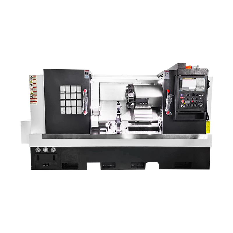 CNC Lathe Machine for High-Precision TurningA CNC lathe positioned for high-precision, efficient turning, with strong rigidity and stability for consistent processing; worth reviewing when specifying turning equipment.View Product →
Four numbers drive almost every result at the spindle, and they are always traded against each other rather than optimized in isolation.
The same program behaves very differently depending on what is in the chuck. A few shop-floor realities:
Most rejects on a lathe trace back to a handful of familiar causes. Chatter from an overhanging boring bar, built-up edge on a dull insert, thermal growth on a long run, and clamping distortion on a thin-wall part all show up as size or finish problems rather than as obvious faults. When a dimension drifts, we check tool wear offsets first, then coolant delivery, then the holding method — usually in that order, because it is the cheapest sequence to rule out. If you want the deeper engineering view of what a lathe can realistically hold, our notes on achievable CNC machining tolerances go through it in more detail.
Plenty of turned parts also need cross holes, keyways or mounting flats. Live tooling solves part of that on a turning center, but some volumes and geometries are simply more economical on a dedicated second machine, where hole-making runs continuously without tying up a lathe. For those jobs we match the process to the part rather than forcing everything through one spindle.
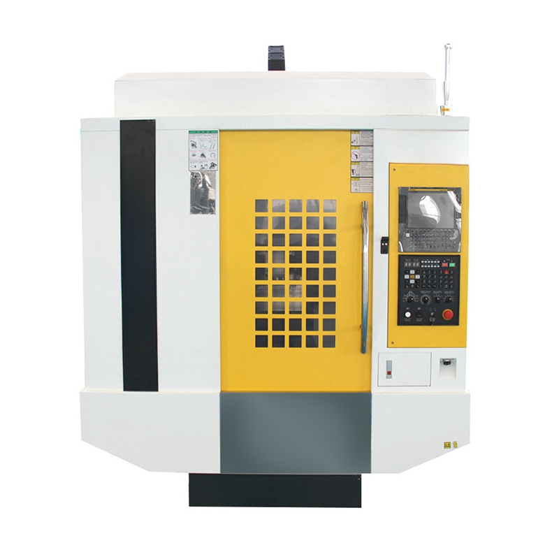 CNC Drilling and Tapping Machine for Dedicated Hole-MakingA drilling and tapping machine for precise, stable processing and heavy-load handling; a dedicated option for continuous hole-making work that would otherwise occupy a lathe.View Product →
Because turning covers rotational geometry so efficiently, the parts travel into almost every industry we serve: drive shafts and flanges for wind power equipment, precision pins and bushings for automation lines and robotic arms, instrument housings and implant components for medical devices, and structural fittings for aerospace assemblies. Each of those sectors pushes different requirements onto the same machine — a shaft that is merely round is easy, while a shaft that must hold concentricity across three diameters after heat treatment is a process problem, not a turning problem.
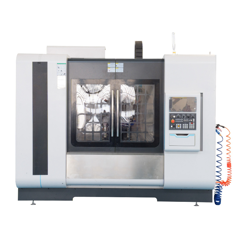 CNC Machining Precision Parts by IndustryCustom high-precision machined components in metals and plastics for aerospace, medical, energy, automotive and automation; organised by industry to help match drawings to existing work.View Product →
It helps to see the range in context. Our CNC machining precision parts pages are organised by the industries they serve, which makes it easier to judge whether your own drawing fits the work we already run.
None of this replaces standing at the machine. A programmer can calculate perfect parameters, but the operator hears chatter before the gauge ever shows it, and feels a chip jam in the coolant line long before a tool breaks. Good turning is a partnership between the code and the person watching it.
If you are working through a part that keeps drifting out of tolerance, or you are choosing between a two-axis lathe and a live-tool turning center for a new program, we are glad to talk it through. Suzhou Heimat Precision Machinery has been machining custom parts and building equipment since 2010, and we are always happy to review a drawing and tell you honestly how it would run. Reach us through our contact page whenever it is convenient.
If you have any questions, please fill out the contact form at the bottom of the page and contact us.
CNC Drilling and Tapping Machin
CNC Lathe Machine
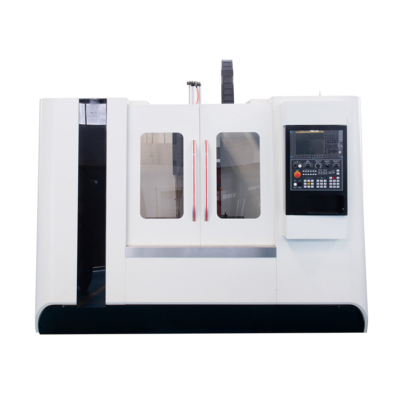 CNC Machine
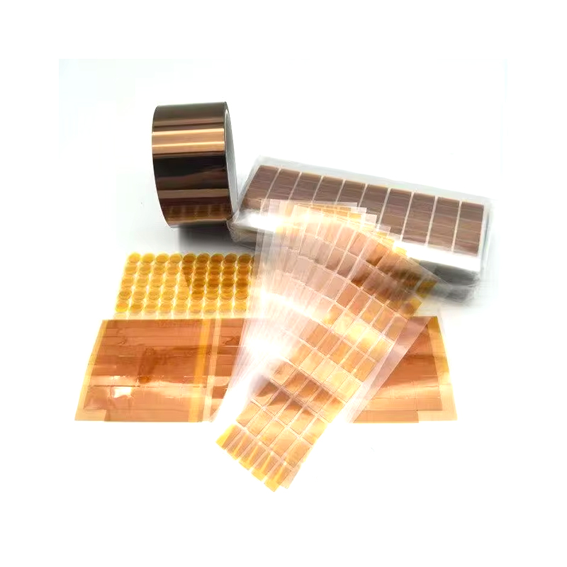 Cutomized Die-Cutting Products for Electronics Industry
 New Energy Automation Die Cutting Products
 Customeized Die-Cut Products in Package Industry
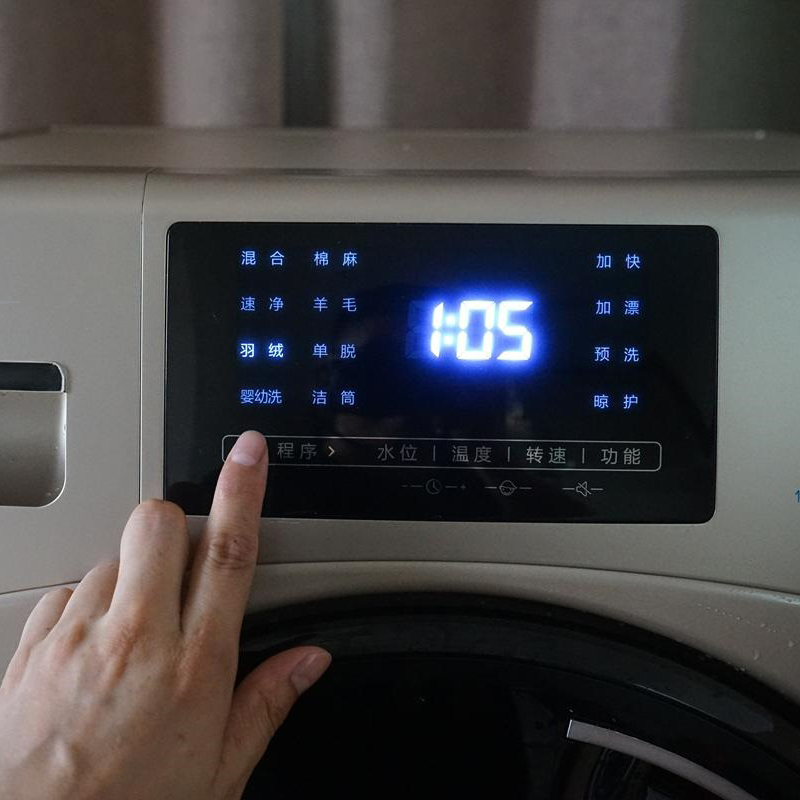 Bespoke Touch Screen for Gaming and Entertainment Devices
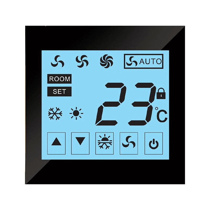 Custom Touch Screen in Smart Home Industry
 Customized Personalized Touch Panel Screen
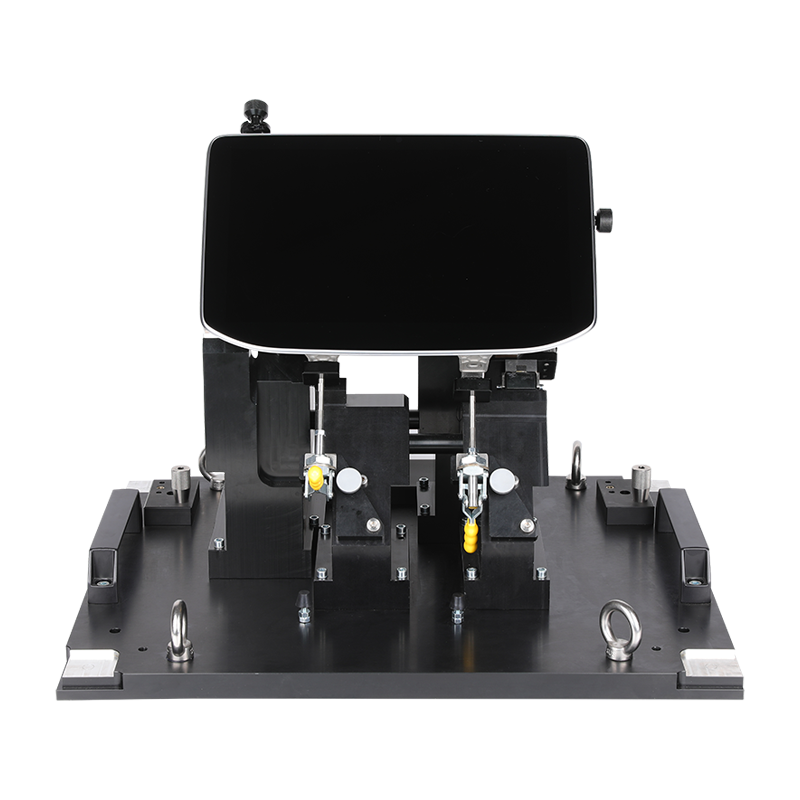 Design Manufacturing and Assembly of Special Customized Custom Electrical Cabinet
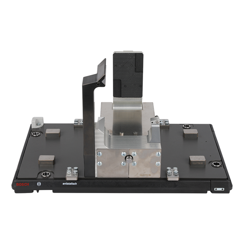 Industrial Robot Automatic Production Line Design Manufacture and Assembly
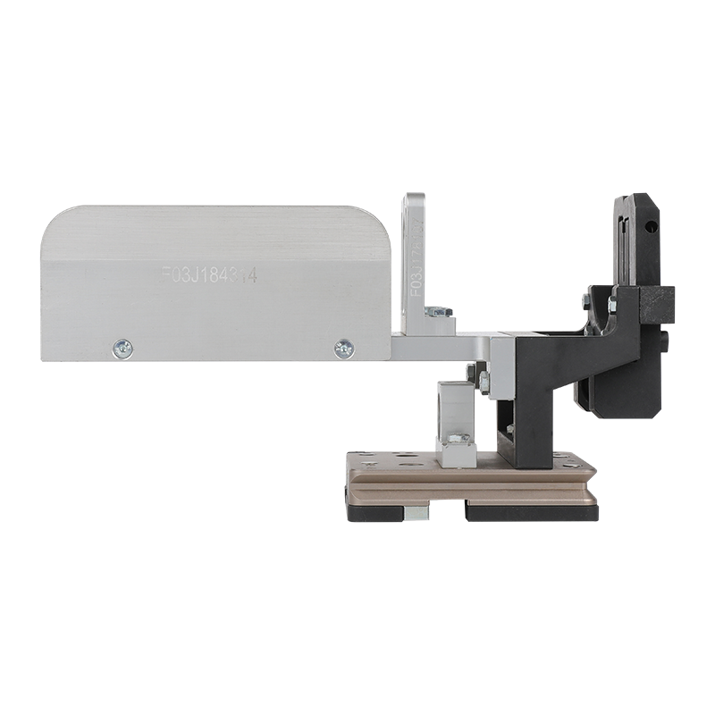 Customized Design Automation Equipment

+86-18118122885

+86-512-66233336

joy.qian@szhengmai.com

No. 8, Guangdian Road, Guangfu Town, Wuzhong District, Suzhou, Jiangsu, China.
Copyright © 2023 Suzhou Heimat Precision Machinery Co., Ltd. All Rights Reserved.Custom CNC Parts Processing Manufacturers

|
